Upper Control Arm Replacement
Warning! The following DIY is under construction and should only be followed if you're experienced enough to fill in the gaps right now!
- Jack and support the vehicle properly on both sides.
- Remove the plastic splash shield below the windshield that covers the upper brace and top of assembly nuts.
- Remove the one rubber panel on each side that covers the view down into the wheel well.
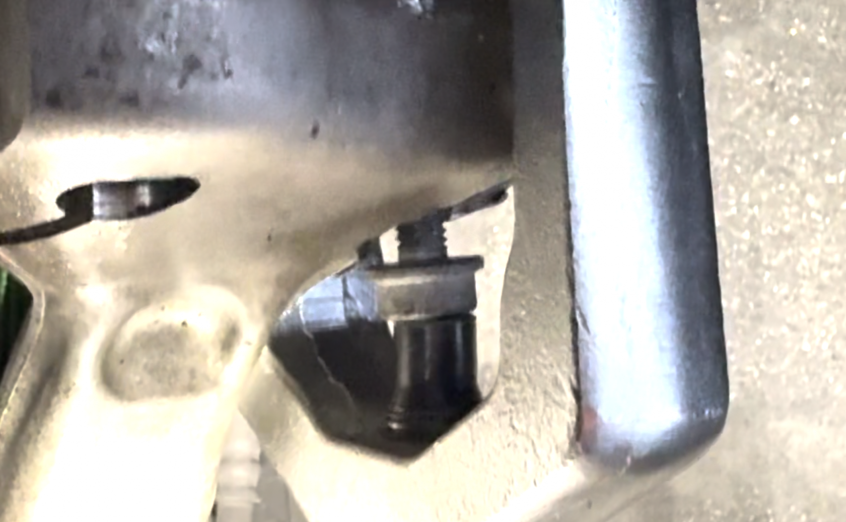
- Hold the level sensor metal bar with a 12mm wrench and use on the opposite side to remove the 10mm nut.
- Remove the upper sway bar end link bolt on both sides.
- Loosen the 16mm bolts on the inside of the upper control arm. Do not remove them yet as you will not be able to get them out.
- Remove the pinch bolt and nut on the upper control arm to hub assembly (the ball joints will remain in the assembly).
- Loosen the upper air assembly nuts (four per side) until they are extremely loose but NOT off.
- Support the wheel hub assembly with a strap going through the view hole or via the official VAG hub adapter tool and your jack.
Failure to support the hub assembly will result in multiple failures and possible injury. You do NOT want to try it unsupported.
- Remove the lower air assembly bolt and nut now. The entire air assembly should be loose and drop down a few inches and be free to wiggle around.
- Use the special ball joint tool and a small bolt to fill the gap because you will run out of threads on the tool more than likely. The triple squares used on the bottom splash shield are a good place to pull one if you can't find anything else. Ensure the hub is supported once again via strap as it can move left/right now with both arms out.
- Your upper control arms should now be loose but still bolted in.
- The air assembly being loose means you should be able to wiggle it around and grab the bolts out. With it loose, you can fit your hand behind the assembly to help guide bolts in and out.
If you can't get the angle right, it's okay to loosen the four nuts entirely and let it drop out but be mindful when jacking the hub back up that it is aligned properly.
- Pull outwards on the upper control arms if they didn't fall out automatically when you removed the bolts.
- Put the new ones in ball joint first - this ensures they seat properly, and you do not have to try and align them while getting them in. Ensure they are aimed at the mounts because you do not want to angle them in once you've seated them.
- Insert the bolts into the upper control arms now. Tighten but do not torque yet as the suspension needs to be loaded before you tighten fully.
- Raise the hub to raise the air assembly ensuring it's aligned properly still.
- Re-attach the air assembly lower bolt into the lower control arm. This can be fun to line up, so the trick is to "wiggle" the hub assembly up and down with the jack while pressing inwards on the bolt. You will visually see the bolt rock at angle as you wiggle it and eventually it'll slide in.
- Torque your new air assembly nuts back to specification (20 Nm / 14 Ft/lb.)
- Re-attach the sway bar end link and leave loose until the suspension is loaded.
- Re-attach the line level sensor stud into the LCA and tighten the nut until snug.
- Raise the hub assembly with the jack so that it is loaded or put the wheels on and put the car on ramps.
- Torque to specification the following: Control Arm Bolts, Sway Bar End Link Upper Bolt.
- Re-install plastic splash shields at top.

Torque Specifications:
| Upper Control Arm to Body Bolts | 50 Nm + 90° | 36 Ft/lb. + 90° |
| Upper Control Arm Pinch Bolt | 40 Nm | 29 Ft/lb. |
| Lower Control Arm to Air Assembly | 90 Nm + 90° | 66 Ft/lb. + 90° |
| Upper Strut Tower to Body | 30 Nm | 22 Ft/lb. |
| Sway Bar Upper End Link Bolts | 40 Nm + 90° |
29 Ft/lb. + 90° |
| Strut Tower Brace | 20 Nm |
14 Ft/lb. |